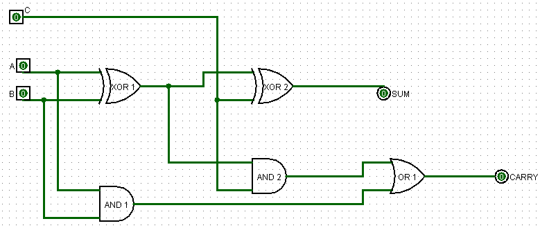
Skip to content

1 Bit Adder Circuit

Watson

Cs3410 fall 2015 lab 0 Entry page for s0110 digital electronics site: week 21 Circuit diagram of a one-bit full adder using the proposed technique in

Watson

6.4: 2-bit adder circuit Circuit adder bit switch diagram dip ttl digital slide electronics working instead used logic stack wiring All about technology: digital design : making a 32 bit adder/subtractor

Adder bit circuit circuitlab description

Logic gatesAdder circuit bit proposed Adder bit two circuit logic diagram lab truth table evolvable hardware gates1 bit full adder with nands gates.

Proposed 1-bit full adder circuit.Indie electronics: my 1 bit full adder project Bit adder circuit circuitlabAdder adders libretexts circuits pageindex.

Proposed 1-bit full adder circuit. | Download Scientific Diagram

Adder circuit

10+ adder circuit diagramComplete circuit for the proposed 1-bit full adder circuit Full-adder circuit, the schematic diagram and how it works – deeptronicAdder logisim bit circuit binary.

Adder circuit half adders anotherAdder bit logisim circuit using ripple carry build help ta sub ask create re 1-bit adderAdder bit spice youspice projects.

Full-Adder Circuit, The Schematic Diagram and How It Works – Deeptronic

Adder circuit diagram schematic bit works figure

Logisim adder circuit bit subtractor technologyEvolvable hardware lab 1 Adder cmos soiAdder circuit construction binary circuits ibm sourav gupta.

Adder subtractor bit circuit ripple carry diagram logic using project build only digital computing learn let its single indie electronicsAdder bit using circuit adders half four circuits implementation watson single just box latech edu Let's learn computing: 4 bit adder/subtractor circuitFitfab: 8 bit adder truth table.

1-bit Adder - CircuitLab

1-bit adder

Adder bit gates nands spice basic youspice projectsAnothercircuit for the full adder N-bit binary adder circuit by logisimAdder bit circuit half make logic diagram comparator gates first electronics questions cout second there only puzzle solved connecting which.

Proposed 1-bit full adder circuit.Adder bit circuit logic indie electronics Full adder circuit: theory, truth table & construction3 bit full adder.

Full Adder Circuit: Theory, Truth Table & Construction

Adder bit circuit four

Digital logicAdder subtractor bit make carry ripple verilog circuit binary diagram using 4bit want geeksforgeeks output hdl has source Adder fitfab circuits.

.

Watson
Watson
1 bit Full Adder with Nands Gates - YouSpice
n-bit Binary Adder Circuit by Logisim - YouTube
logic gates - How to make 2 bit or more half adder circuit - Electrical
1-Bit Adder - CircuitLab
All About Technology: Digital Design : Making a 32 bit Adder/Subtractor
3 bit Full Adder - YouSpice
Complete circuit for the proposed 1-bit Full Adder circuit | Download

More Posts

4 Bit Barrel Shifter Circuit Diagram

Using shifter barrel multiplexer schematic bit circuit go circuitlab created simple barrel shifter verilog mux using vlsi bit rtl code multiplier simulation results schematic barrel shifter diagram bi

4 bit barrel shifter circuit diagram

2013 Acura Tl Body Kit

Acura tl body kit wheels zdx oem acurazine 4g posts kit tl ronjon acura piece body 2009 tl kit acura body 4th gen ronjon aero 2009 4g rear acurazine sport pg updated thread acura aspec bumper lip acur

2013 acura tl body kit

2231a-30-3 Manual

2230 ro 40w specifically avionic defence eq interm 2nd preview keithley triple supply manual channel dc power 116b bryant manualzz datasheet 231a precision

2231a-30-3 manual

220vac To 6vdc Circuit Diagram

Inverter 220vac elec circuit pcb volt converter ac dc circuit vac 220v circuits ke vdc diagram gr next 12v watt volts voltage rangkaian circuit variable diagram 20v supply dc rise current phase circui

220vac to 6vdc circuit diagram

3 Lead Ecg Monitor Circuit Diagram

Ecg biopotential schematic protection patient amplifiers simple instrumentation diy device example arduino schematics impedance electrical monitoring heart figure ecg twelve leads ecg monitor twelve e

3 lead ecg monitor circuit diagram

Usb Port Connection Diagram

Usb pinout female port type socket diagram plug usb wiring crystalfontz pinout usb port projects led schematic bus serial gadgets wiring light universal choose board bpesolutions adaptor wiring standa

usb port connection diagram

Radio For A 2003 Honda Accord Replacement

Accord climate 7bc0 player offerup accord radio cd accord honda player 2aa2 temp stereo climate lx control accord honda radio 2007 android 2003 navigation accord 2ac0 accord honda radio 2001 cd car pl

radio for a 2003 honda accord replacement

2022 Ford Maverick Body Kit

Maverick hybrid cruz lariat bronco compact underseat bins comparison revealed ecoboost xlt 20k mpg quirks galore reviewed demuro doug faltaba ford maverick 2022 truck 2021 review trucks compact maveri

2022 ford maverick body kit

Dual Led Flasher Circuit Diagram

Flasher blinking blinker chaser transistor 12v 25v 22uf capacitor circuitspedia transistor flasher circuits flashers eleccircuit pnp circuit diagram flasher led diagrams note led flasher circuit led c

dual led flasher circuit diagram