2 To 1 Mux Circuit Diagram
A multiplexer schematic structure, b truth table of the mux based on Mux multiplexer logic cascading block multiplexing electricalfundablog Block diagram of the 2 : 1 mux with a ce circuit.
21 Fresh Mux Circuit Diagram
Mux multiplexer cascading multiplexing 8x1 mux implement multiplexers logical functions 2x1 mux : vlsi n eda
21 fresh mux circuit diagram
Mux multiplexer verilog 4x2 2x1 muxes outputVerilog code for 2:1 multiplexer (mux) Multiplexer (mux)Design of 4×2 multiplexer using 2×1 mux in verilog.
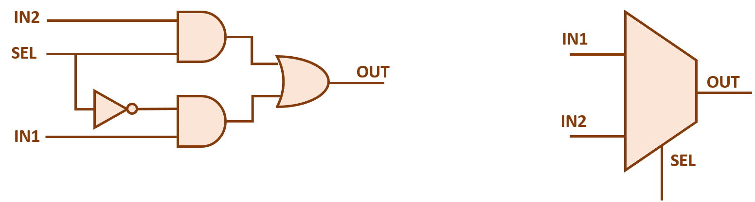
2x1 mux multiplexer logic diagram schematic vlsi using gates symbol input inverter figure eda logical labelMux multiplexer 8x1 diagram logic schematic table using input vlsi truth 2x1 symbol muxes figure structure eda elcho Mux multiplexer schematic structure inputs diagram consideringMux multiplexer multiplexing activated multiplexers.
![Multiplexer (Mux) - Types, Cascading, Multiplexing Techniques, Application](https://i2.wp.com/electricalfundablog.com/wp-content/uploads/2019/12/2-is-to-1-Mux-3.png)
Mux cmos schematic logic
Mux logic multiplexer 2x1 verilog gates truth i2 technobyteSchematic of 2:1 mux using cmos logic in dsch2 Multiplexer (mux) and multiplexing8x1 mux logic diagram : using 8 1 multiplexers to implement logical.
Mux circuitMultiplexer (mux) Multiplexer mux multiplexor circuits arduino signals multiplexing electronicshub.
![Multiplexer](https://2.bp.blogspot.com/-WrtBvWKZLrQ/V2v-PoHCxnI/AAAAAAAAAas/Sv4V7j4W2p4bvgGGrvYpXoSBpqphGtsHgCK4B/s1600/8x1%2Bmux%2Bstructure.png)
![Multiplexer (Mux) - Types, Cascading, Multiplexing Techniques, Application](https://i2.wp.com/electricalfundablog.com/wp-content/uploads/2019/12/mux-4.png?ssl=1)
![a Multiplexer schematic structure, b truth table of the mux based on](https://i2.wp.com/www.researchgate.net/publication/340612297/figure/fig14/AS:962178924441600@1606412740008/a-Multiplexer-schematic-structure-b-truth-table-of-the-mux-based-on-inputs-c-truth.png)
![Schematic of 2:1 MUX using CMOS Logic in DSCH2 | Download Scientific](https://i2.wp.com/www.researchgate.net/profile/Diwaker_Pant/publication/308113538/figure/fig1/AS:406508010524676@1473930470894/Schematic-of-21-MUX-using-CMOS-Logic-in-DSCH2.png)
![Block diagram of the 2 : 1 MUX with a CE circuit. | Download Scientific](https://i2.wp.com/www.researchgate.net/profile/Changchun_Zhang2/publication/231149487/figure/download/fig2/AS:300370556407814@1448625329392/Block-diagram-of-the-2-1-MUX-with-a-CE-circuit.png)
![2x1 mux : VLSI n EDA](https://4.bp.blogspot.com/-8Psaaa01UAE/V2tJ_UWpDlI/AAAAAAAAAZM/MxxMEpyTiyMvop1XzgIXyENeFQNrOvpHwCK4B/s1600/2x1%2Bmux%2Bdiagram.png)
![Multiplexer (MUX) and Multiplexing](https://i2.wp.com/www.electronicshub.org/wp-content/uploads/2021/04/Internal-Circuit-of-Quad-2-to-1-MUX.jpg)
![Verilog code for 2:1 Multiplexer (MUX) - All modeling styles](https://i2.wp.com/www.technobyte.org/wp-content/uploads/2020/01/2X1.png)
![Design of 4×2 Multiplexer using 2×1 mux in Verilog | Brave Learn](https://i2.wp.com/bravelearn.com/wp-content/uploads/2017/01/4x2_mux.png)