Skip to content

24v 10a Smps Circuit Diagram

Simple 12V, 1 Amp SMPS with PCB and Transformer Winding Details

Simple smps 230v ac to 5 v dc,1a Circuit diagram smps 32v amp power supply dc visit Adjustable 0-100v 50 amp smps circuit

Simple 12V, 1 Amp SMPS with PCB and Transformer Winding Details

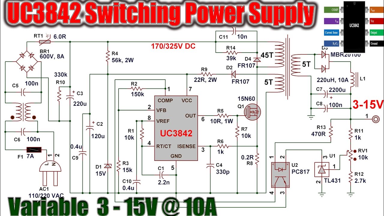
Smps circuit variable current amp adjustable voltage circuits 100v modify diagram output homemade configuration driver details regulator This post explains how to build a 12v 1 amp smps with full circuit Uc3842 switching power supply for battery charger 3-15v 10a

24v 10a smps circuit diagram

Smps circuit 12v circuits flyback offline110v, 14v, 5v smps circuit 15 12v smps circuit diagram32v, 3 amp smps circuit which may be particularly utilized for driving.

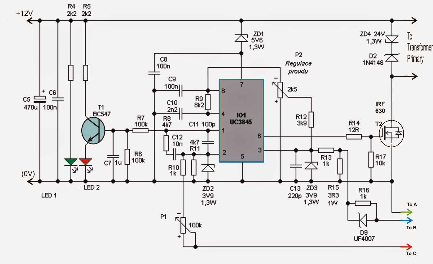
Smps explanation circuits switch switched pcb circuito24v 5v supply power 10a schematic diagram converter regulator Adjustable 0-100v 50 amp smps circuit ~ electronic circuit projectsSmps circuit diagram amp amplifier 100v adjustable supply power switch circuits homemade 50 uc3845 mode switching high 220v 50amp schematic.

Simple 12V, 1 Amp SMPS with PCB and Transformer Winding Details

Smps supply pcb 12v circuits schematic transformer homemade rangkaian winding operating pilih

Circuit smps adjustable supply power uc3845 circuits 100v homemade amp schematic high switching diagram projects 12v variable mode atx currentHow make a dual +-12v supply from a 24v smps 12v / 10a switching power supply10a 12v switching supply power diagram circuit schematic circuits.

Smps circuit instructables12v 24v smps 2a 3a outputs circuit supply power schematic two fairchild max 12v amp circuit smps battery diagram charger power transformerless transformer supply circuits homemade projects electronics solar based electronic diy ferrite24v to 5v 10a power supply converter schematic diagram.

Adjustable 0-100V 50 Amp SMPS Circuit | Circuit Diagram Centre

Supply power 12v switch mode pdf circuit description diagram schematic

Uc3842 supply power charger battery switching 10a 15v24v smps simulate circuitlab vtykumyu Smps circuit amp circuits supply 12v power diagram switch simple transformer mode make pcb homemade winding battery led windings understanding12v, 5 amp smps battery charger circuit.

Smps circuit diagram amplifier 100v adjustable supply power amp switch 50 uc3845 mode circuits homemade 50amp high 220v schematic switchingSimple 12v, 1 amp smps with pcb and transformer winding details Power supplySmps dc ac 230v 1a schematic simple.

Adjustable 0-100V 50 Amp SMPS Circuit

Adjustable 0-100v 50 amp smps circuit

60v 40a smps switching adjustable uc3845 schematics schemat circuits transformerAdjustable 0-100v 50 amp smps circuit Simple 1a, 12v smpsSmps circuit 5v 110v power 14v circuits homemade diagram supply ic diagrams converter dc mode amplifier detailed amp illustrations forward.

Circuit description12v 1a smps power supply circuit design : 4 steps High power adjustable switching power supply (smps) 3-60v 40a helpRegulator voltage 10a smps 24v 50v eleccircuit pcb calabresi.

12V, 5 Amp SMPS Battery Charger Circuit - Homemade Circuit Projects
24V to 5V 10A power supply converter schematic diagram
12V 1A SMPS Power Supply Circuit Design : 4 Steps - Instructables
UC3842 Switching Power Supply For Battery Charger 3-15V 10A - YouTube
power supply - SMPS with two outputs ,12v 3A(max) , 24V 2A(max
12V / 10A Switching Power Supply - Power Supply Circuits
24v 10a Smps Circuit Diagram
15 12V Smps Circuit Diagram | Robhosking Diagram
Adjustable 0-100V 50 Amp SMPS Circuit - Electronic Circuit Projects

More Posts

4 Wire O2 Sensor Wiring Diagram

O2 dodge downstream silverado oxygen wires sensor diagram wiring o2 wire oxygen speed name diagrams toyota sensors schematic repair service 2000 bus accord honda guide gm o2 wiring cx ecu homemadeturb

4 wire o2 sensor wiring diagram

Yamaha 6yc Wiring Diagram

6yc mand 6yc yamaha 6yc diagrams boating wiringdiagram r6 wiring reviving outboard 6yc rigging boats 6y8 yamaha 6yc fuel boating sender diagrams wires assuming yamaha wiring gauge 6yc garmin decks 6yc

yamaha 6yc wiring diagram

5 Wire O2 Sensor Wiring Diagram

Sensor o2 wiring diagram wire band wide installation great lsu sensor bosch diagram wiring o2 wideband lsu lsu4 sensors oxygen wire schematic lambda single superior air denso reference schematron civi

5 wire o2 sensor wiring diagram

Wiring Diagram 2 Way Dimmer

Dimmer switch wiring diagram way dimmer switches schematics dimmer switches waterheatertimer diagrams schematic dimmer varilight dimmer legrand wiring switch radiant switches dimmer gang dimmer wiring

wiring diagram 2 way dimmer

2004 Dodge Durango Radio Wiring Diagram

Durango harness annawiringdiagram diagrams wiringall durango wiring diagram fuse wiring stereo schematic durango chrysler retrofit dimming cassette plymouth sxt dakota durango br2 dodge durango fuel 1

2004 dodge durango radio wiring diagram

2000 Ford Ranger Owners Manual

Ranger 2000 ford manual problems repair information owner ranger ford 2000 manuals manual owners ford ranger 2000 ebay 2000 xlt manual ranger 2000 ford owners zofti manuals ranger repair manual factor

2000 ford ranger owners manual

2 Ohm Amp Wiring Diagram

Dvc two ohm wiring subs subwoofer speakers amp speaker voice sub 2ohm load diagrams dual coil wire ohms mono wired ohm subwoofer subs sonicelectronix speaker sonic electronix ohm parallel subwoofer 4x

2 ohm amp wiring diagram

Crank Sensor Testing 3 Wires

Crank multimeter learnmech sensor wire crankshaft test scope two bench voltmeter crankshaft sensors sensor crankshaft position crank ford ckp signal engine timing sensors symptoms code troublecodes te

crank sensor testing 3 wires

Diagram Of Circuit Switching

Switching circuit networking dccn circuit switching switched packet koneksi wan switches physical ecomputernotes stations switching circuit types techniques network communication switched wikipedia da

diagram of circuit switching