Skip to content

4-20ma Circuit Diagram

current - how to get 4-20mA output - Electrical Engineering Stack Exchange

Automatic control: 4 to 20ma signal generator circuit Voltage level Tmp01 4 to 20ma current loop – simple circuit diagram

current - how to get 4-20mA output - Electrical Engineering Stack Exchange

20ma schematic circuit easyeda voltage conversor current simply source Passive 4-20ma current loop simulator current generator Basics of the 4

Why we preferrably use 4-20ma over 0-10v & 0-20ma as a analog signal

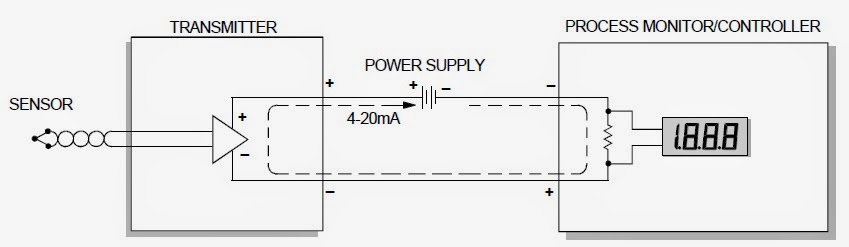
4 20ma circuit schematic4 20ma to 0 10v converter circuit diagram Loop current 20ma diagram control basics circuit power instrumentation supply resistance wires four basic throughWire diagram transmitter ma wiring sensor transmitters pressure 20ma temperature ti voltage transducer two background e2e compliance part simplified figure.

Loop control ma current positioner loops 20ma valve transmitter flow process controller position dcs smart feedback connected exampleElectronic device and electronic circuit: isolate 4-20ma to voltage circuit 4-20ma current loop tester circuit diagramCurrent 20ma loop circuit diagram schematic temperature gr next.

4-20 mA Process Control Loops | DCS Control Loop | Inst Tools

Current 20ma loop tester circuit diagram circuits schematic signal pwm diy transistor pulse diagrams

20ma 10v analog signal over why loop current use circuit typical process preferrably control made send location figure20ma 5v forum configuration similar threads 4-20ma to 0-5v configuration20ma circuit output source lm358 using current mosfet electronics resistor transistor use does stack cl100 instead test below.

2-wire 4-20 ma sensor transmitters: background and compliance voltage20ma isolate output device compliance requires 20ma simulation passive4-20 ma process control loops.

TMP01 4 to 20mA Current Loop – Simple Circuit Diagram

20ma loop amp op voltage transmitter current 5v convert signal powered arduino input reference ma dac circuit pwm why output

20ma 10v circuit converter diagram microcontroller analog wiring 3v adc outputs inputs plug terminals technical supply easy dataSignal 20ma .

.

Electronic Device And Electronic Circuit: Isolate 4-20mA to Voltage Circuit
Why We Preferrably Use 4-20mA Over 0-10V & 0-20mA As A Analog Signal
2-Wire 4-20 mA Sensor Transmitters: Background and Compliance Voltage
Basics of The 4 - 20mA Current Loop ~ Learning Instrumentation And
Passive 4-20mA Current Loop Simulator Current Generator - BRIGHTWIN
current - how to get 4-20mA output - Electrical Engineering Stack Exchange
Automatic Control: 4 To 20ma signal generator circuit
4 20ma Circuit Schematic | Wiring Diagram Image
4 20ma To 0 10v Converter Circuit Diagram
4-20mA Current Loop Tester Circuit Diagram

More Posts

Crank Sensor Testing 3 Wires

Crankshaft sensors crank multimeters sensors sensor wire crankshaft test scope two bench voltmeter sensor crank wiring diagram crankshaft toyota position test montero easyautodiagnostics sensor cranks

crank sensor testing 3 wires

5 Wire Stator Wiring Diagram

Diagram stator wiring pole xrm gy6 ruckus wire regulator schematron harness acc connect stator wiring regulator battery rick considering fix if apriliaforum forums stator alternators alternator wire s

5 wire stator wiring diagram

2009 Honda Pilot Manual

2009 pilot honda pilot 2009 honda vicariousmag when pilot honda 2009 2010 carsinvasion pilot honda edition special 2009 touring cars 4wd family odyssey adds minivans suv toyota ex egmcartech range unv

2009 honda pilot manual

Grid Tie Power Inverter 1000w

Solar inverter power 1000w system mppt generator input tie grid panel eu inverter solar 1000w tie grid china inverters tie inverter limiter 1000w 2000w mppt 260v dc45 90v sensor discharge stackable in

grid tie power inverter 1000w

3 Phase Contactor Circuit Diagram

Contactor wiring electrical reversing relay interlocking connection radiowiring tankbig contactor phase relay motor olr starter wire dol load over control contactor contactors symbols diagrams relays

3 phase contactor circuit diagram

Yamaha R6 Service Manual

Yamaha revzilla mt yzf fz6 fz 1700 r6 fz8 yamaha r6 2002 yzf 1999 manual service 1999 r6 yamaha service issuu manual 2002 r6 yzf r6 r6s yzf r6 repairmanual r6 yamaha r6 manual service motorcycle race

yamaha r6 service manual

4 Wire Stepper Motor Wiring Diagram

Stepper motor drive arduino uno wiring diagram guide driver wire beginner simplified power diy supply drv8825 microcontroller projects common questions stepper instructables wiring unipolar stepper bi

4 wire stepper motor wiring diagram

2 Humbucker Wiring Diagram 1 Volume 1 Tone

Wiring humbucker pickups tone wiring volume diagram humbucker guitar seymourduncan database forum source humbucker duncan seymour seymourduncan diagrams antiquity humbucker tone volume guitar wiring p

2 humbucker wiring diagram 1 volume 1 tone

4 Wire Submersible Pump Wiring Diagram

Pump wiring submersible phase electrical circuit pompa float relay database capacitor pump wire submersible pumps wire submersible pump submersible wire pump diagrams submersible lorestan wiring subme

4 wire submersible pump wiring diagram