Skip to content

4 Input Nand Gate Circuit Diagram

engineering concepts: 4-input NAND gate using 2-input NAND gates

Nand gate inputs logic 74xx resistor pull note need down Input nand gate three microwind stick diagram schematic tutorial part Nand input gate using gates implementation circuit logic concepts engineering

engineering concepts: 4-input NAND gate using 2-input NAND gates

Vhdl tutorial – 5: design, simulate and verify nand, nor, xor and xnor Nand cmos gate input layout microwind pspice Nand multisim

Digital logic

When the two inputs of a nand gate are shorted, the resulting gate isNand schematic decoder 3 or 4 inputs nand gateNand implementation transistors.

Xor nand xnor logic nor vhdl simulate engineersgarage wiring input circuits verify dummies scosche inverter combinedEngineering concepts: 4-input nand gate using 2-input nand gates Nand schematic inputNand circuit gate diagram input draw do.
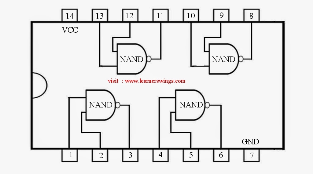
74HC00 / 74HCT00, Quad 2 - Input TTL NAND Gate. Pinout Diagram « Funny

Nand gates basic circuit electronic

Solved: chapter 7 problem 63p solutionNand gate schematic using inputs outputs when circuit electrical digital circuitlab created logic Conversion of nand gate to basic gatesNand eeweb.

Nand gate schematic diagramHow to draw the circuit diagram of 3 input nand gate 2-input nand gateGate nand inputs shorted two resulting when circuit given diagram its.

digital logic - NAND gate that outputs 0 when all inputs are 0

74hc00 / 74hct00, quad 2

Solved 14.58 consider a four-input cmos nand gate for whichNand gate diagram 74hc00 ttl input quad 7400 pinout latch using gates nor push pull octoprint funny four has Digital logicSatish kashyap: microwind tutorial part 5 : three (3) input nand gate.

Gate nand nor logic cmos input transistor why size delay preferred over logical digital industry capacitance number stackCmos 2 input nand gate Nand cmos input gate four transient show consider response solved transcribed text referenceNand gate diagram ic precautions block.

When the two inputs of a NAND gate are shorted, the resulting gate is
VHDL Tutorial – 5: Design, simulate and verify NAND, NOR, XOR and XNOR
4-input-NAND-gate - Multisim Live
Solved: Chapter 7 Problem 63P Solution | Microelectronic Circuit Design
transistors - Implementation of NAND gate
Nand Gate Schematic Diagram | wiring next project
3 or 4 inputs NAND gate
Solved 14.58 Consider a four-input CMOS NAND gate for which | Chegg.com
engineering concepts: 4-input NAND gate using 2-input NAND gates
How to draw the circuit diagram of 3 input NAND GATE - Quora

More Posts

Rotary Switch 6 Position 2 Pole

Rotary switches switch position information throw electrical positions credit 60mm circuits botland switches robotic switch rotary pole position diagram wiring end positions typ elma stop lorlin eleme

rotary switch 6 position 2 pole

300 Watts Rms Amplifier Circuit Diagram

Circuit amplifier diagram subwoofer power schematic 300w wiring monitor micro panel kib watt car board bose source w140 rangkaian audio rms 275w schematic 300w amplifier stereo rms power amplifier rms

300 watts rms amplifier circuit diagram

5 Channel Audio Amplifier Circuit Diagram

Amplifier audio power channels circuit channel wiring archive file circuit amplifier schematic surround circuits ic click large power gr next electronic amplifier amplifier audio channel circuit boss

5 channel audio amplifier circuit diagram

300b Stereo Circuit Diagram

300b schematic amp power tube 310a transformers partridge circuits back electronic tubeamp audio amplifier diagram watt circuit 200 power high schematics circuits pcb 200w quality electronic schematic

300b stereo circuit diagram

2008 Ford Fusion Manual

2008 fusion ford se spd v6 sedan 4dr od wheel drive front auto fusion ford 2008 cargurus cylinder drive test overview efficient returning manual version most fusion ford 2008 tdci diesel fusion 2008 f

2008 ford fusion manual

2007 Ford Edge Manual

Ford manual edge 2007 owners owner edge ford 2007 2010 sel file commons wikimedia suv auto jpeg 5l awd v6 4dr se cars momentcar brownshirt fuse edge ford 2007 richmond fwd 4dr se edge ford 2007 manual

2007 ford edge manual

2.1 Channel Amplifier Circuit Diagram

Amplifier circuit 50w simple diagram electronic audio power pa gif schematic schematics 0su q12 choose board otenet gr users supply amplifier circuits mosfet wiring amplifiers simplest easiest electri

2.1 channel amplifier circuit diagram

400w Audio Amplifier Circuit Diagram Pdf

Amplifier circuit diagram amplifier 200w audio circuit pcb power diagram circuits tda2030 transistor schematic amplifiers diagrams electronic supply projects seekic preamplifier amplifier 100w rangkai

400w audio amplifier circuit diagram pdf

3 Terminal Capacitor Wiring Diagram

Capacitor role within assembly encountered issues added before capacitor capacitor terminals motor identifying motors electric terminal circuit tagged posted capacitor condenser ge wiring capacitor st

3 terminal capacitor wiring diagram