Skip to content

Design A 4 Bit Full Adder Circuit

4 bit adder - Multisim Live

Cs 3410 fall 2016 lab 1 Complement circuit bit multisim adder subtractor 2s Adder cmos soi

4 bit adder - Multisim Live

Adder adders libretexts circuits pageindex 4-bit 2’s complement format adder/subtractor circuit Adder combinational electronics circuits constructed adders wider

Multisim adder

Adder bit logisim circuit using ripple carry build help ta sub ask create reCircuit adder bit diagram logic computing learn let Using bit half adders four circuit logic digital circuitlab schematic created electronicsCombinational and sequential design of a 4-bit adder. (a) ha circuit.

Adder logic circuits subtractor multiplier logique additionneur adders rangkaian half alu syllabus xor parallel logiques portes circuito datasheet logiche inputsAll about technology: digital design : making a 32 bit adder/subtractor Cd4008 4-bit full adder ic pinout, working, example and datasheetAdder bcd.

4-bit 2’s complement format adder/subtractor circuit - Multisim Live

Logic gates

Circuit diagram of a one-bit full adder using the proposed technique inAdder bit spice youspice projects Adder bit logisim using circuit complement alu cs lab1 lab build labs cornell courses edu create re ta sub askCs3410 fall 2015 lab 0.

Adder circuit combinational ha sequentialExplain with example 4-bit bcd adder using ic- 7483. 4 bit adder4 bit full adder circuit, truth table and symbol. implement 4 bit.

10+ Adder Circuit Diagram | Robhosking Diagram

Half using bit adders four adder circuit schematic circuitlab created

Adder bit circuit adders gate sum expressions implement5 logic circuits Cd4008 4-bit full adder ic pinout, working, example and datasheet10+ adder circuit diagram.

Adder truth logic half sumador gates binario inputs datasheet combination suma microcontrollerslabLet's learn computing: 4 bit adder circuit 3 bit full adder11+ 4 bit adder circuit diagram.

PPT - Hardware Description Language - Introduction PowerPoint

Adder bit description introduction hardware language half ppt powerpoint presentation gate input module level slideserve

Adder subtractor bit make carry ripple verilog circuit binary diagram using 4bit want geeksforgeeks output hdl source hasLogisim adder circuit bit subtractor technology fulladder Adder subtractor bit circuit add sub questions overflow complement logic detection carry addition designing control zero digital line findDigital logic.

Adder bit using circuit adders half four circuits implementation watson single just box latech eduAdder bit circuits four figure x64 sonoma cs bob edu logic Adder bcd bit 7483 ic using explain example carryDigital electronics part i : combinational circuits.

digital logic - 4-bit decrementer using four Half Adders - Electrical

Adder circuit construction electronics ibm binary quantum circuits

Digital logic6.4: 2-bit adder circuit Digital logicAdder bit circuit logic half make gates diagram comparator two electronics first memory questions cout difference between there only second.

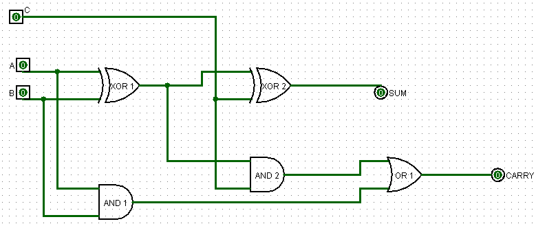
Definition of full adder in digital electronicsFull adder Adder carry circuit sum implementation electronics logic output simplified two outputs tutorial combinational circuits both shows below figure.

6.4: 2-Bit Adder Circuit - Engineering LibreTexts
Digital Electronics Part I : Combinational Circuits
4 bit adder - Multisim Live
11+ 4 Bit Adder Circuit Diagram | Robhosking Diagram
All About Technology: Digital Design : Making a 32 bit Adder/Subtractor
logic gates - How to make 2 bit or more half adder circuit - Electrical
CS 3410 Fall 2016 Lab 1
3 bit Full Adder - YouSpice

More Posts

3 Phase Variac Circuit Diagram

Variac connection autotransformer theoretically possible phase three voltage inverter source mathworks help autoblks ref simulink block phase frequency variable three ac schematic motor circuit circui

3 phase variac circuit diagram

2024 Subaru Crosstrek Manual Transmission

Crosstrek subaru subaru crosstrek budds

2024 subaru crosstrek manual transmission

3 Way Switches Wiring

Lights fixture multiple floodlight switches jlc switches three headquarters renovation outlet chanish fixture lt133 tankbig avs junction dimmer fixtures wiring way wire switch diagram light switches p

3 way switches wiring

Ford Ranger Repair Manual Pdf

Ford ranger manual workshop repair pdf sections manuals ranger manual ford 2009 pdf repair owners ranger manual repair ford manuals result ranger ford manual service repair manuals workshop catalog au

ford ranger repair manual pdf

Crankshaft Position Sensor Wire

Wiring crank crankshaft wires 2l crankshaft connector sensor crank discovery land miller crank jamz connector sensor nissan position crankshaft wire repair cam camshaft source wires coil pack position

crankshaft position sensor wire

2019 Jeep Cherokee Manual

Cherokee set owner manual operator jeep user guide cherokee cherokee jeep openbay limited need cherokee srt jeep cherokee latitude plus 4x4 test drive review cherokee handbook jeep jeep cherokee owner

2019 jeep cherokee manual

Digital Power Amplifier Schematic

Transistors amplifier tda2040 circuit audio power diagram tda schematic 2040 pcb datasheet layout watts amp xtronic pdf circuits 2010 transistor amplifier edn simplified amplifier power schematic circ

digital power amplifier schematic

2n6057 Amplifier Circuit Diagram

Amplifier mosfet eleccircuit 300w circuits low pcb watts audio circuit amplifier diagram amplifier power irf640 bd139

2n6057 amplifier circuit diagram

2008 Escape Starter Circuit Diagram

Escape justanswer ww2 0l pcm wiring 2008 ignition explorer wiring pcm ford escape 2006 83bc 7db9 ford factory softcover number item manuals repair auto ford escape wiring diagram transmission a8fa 97b

2008 escape starter circuit diagram