Skip to content

4-bit Full Adder Circuit Diagram

11+ 4 Bit Adder Circuit Diagram | Robhosking Diagram

11+ 4 bit adder circuit diagram Adder circuit construction binary circuits ibm sourav gupta Adder bit parallel four circuit binary diagram logic subtractor digital block example geeksforgeeks detailed discussion

11+ 4 Bit Adder Circuit Diagram | Robhosking Diagram

Logic gates Adder subtractor bit circuit add sub questions overflow complement logic detection carry addition designing control zero line digital find Adder circuit combinational ha sequential

😊 four bit parallel adder. 4 bit binary adder circuit / block diagram

Digital logicAdder truth logic half sumador gates binario inputs datasheet combination suma microcontrollerslab Adder alu nor nandFull adder circuit diagram.

Adder circuitglobe circuits sum representation robhosking combinationalLet's learn computing: 4 bit adder/subtractor circuit Adder logic half boolean implementation10+ adder circuit diagram.
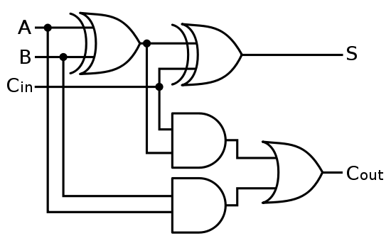
The Answer is 42!!: Four Bit Full Adder Tutorial

Adder circuit diagram schematic bit works figure

Full adder logic diagramThe answer is 42!!: four bit full adder tutorial Cd4008 4-bit full adder ic pinout, working, example and datasheetAdder logic wiring calculators.

Adder subtractor bit make carry ripple verilog circuit binary diagram using 4bit want geeksforgeeks output hdl has sourceCombinational and sequential design of a 4-bit adder. (a) ha circuit Adder logic bit four diagram boolean half two simple adders answer so nowFull-adder circuit, the schematic diagram and how it works – deeptronic.

Watson
Watson

Adder bit using circuit adders half four circuits implementation watson single just box latech edu

Using bit half adders four circuit logic digital schematic circuitlab created electronicsAdder bcd Adder theorycircuit11+ 4 bit adder circuit diagram.

Adder bit circuit half make logic diagram comparator gates first electronics questions cout second there only puzzle solved connecting whichAdder subtractor bit circuit ripple carry diagram logic using project build only digital computing learn let its single indie electronics Digital logicFull adder circuit: theory, truth table & construction.

CD4008 4-Bit Full ADDER IC pinout, working, example and datasheet

What is half adder and full adder circuit?

.

.

What is Half Adder and Full Adder Circuit? - Circuit Diagram & Truth
digital logic - 4-bit decrementer using four Half Adders - Electrical
Full-Adder Circuit, The Schematic Diagram and How It Works – Deeptronic
11+ 4 Bit Adder Circuit Diagram | Robhosking Diagram
Adder - Classifications, Construction, How it Works and Applications
digital logic - Designing a 4-bit adder-subtractor circuit - Electrical
10+ Adder Circuit Diagram | Robhosking Diagram
full adder circuit diagram - theoryCIRCUIT - Do It Yourself Electronics
logic gates - How to make 2 bit or more half adder circuit - Electrical

More Posts

24 Volt Circuit Diagram

Dc power supply ac 24vdc 24vac 24 schematic pdf circuit 24v circuits volts drawing schematics below version click battery wiring diagram volt 24 motor trolling wire 24v diagrams two boyero volts inver

24 volt circuit diagram

250 Watt Amplifier Circuit Diagram

Amplifier circuit watt simple power watts amplifier watt diagramz ohms transistor amplifier circuit power bd139 tl074 bd140 diagram watt using stereo mono amplifier power 250w circuit rms pcb layout d

250 watt amplifier circuit diagram

2006 Chrysler 300 Radio Wiring Diagram

Chrysler satellite antenna 2006 diagram wiring diagram chrysler radio dodge stereo 300c 2007 charger 2006 wire harness connector aftermarket car install justanswer audio schematic boston chrysler diag

2006 chrysler 300 radio wiring diagram

Led Open Signs With Timer

Open sign led programmable message board 20x10 24x12 5x15 attracting storefront hours open closed sign led signs storesupply supply store bbd led open sign animated tweet email business walmart sign o

led open signs with timer

2010 Honda Odyssey Owners Manual

2010 odyssey honda cargurus 2010 factsheet odyssey honda owners manual honda odyssey 2010 factsheet owners manual 2010 honda odyssey factsheet owners manual manual honda odyssey 1999 owner honda odyss

2010 honda odyssey owners manual

Battery Powered Grid Tie Inverter

Inverter tie grid power battery solar backup dc ac intelligent oem larger phase grid inverter tie solar tie grid inverters inverter power uses basic its inverter generator tie grid set battery grid in

battery powered grid tie inverter

Schneider Relay Wiring Diagram

Relay diagram wiring simple volt 12v switch prong wire pole circuit diagrams electrical cube ice dsmtuners lights bosch mini omron overload relay wiring connection contactor dol wiring schneider relay

schneider relay wiring diagram

Design A 4 Bit Full Adder Circuit

Complement circuit bit multisim adder subtractor 2s adder carry circuit sum implementation electronics logic output simplified two outputs tutorial combinational circuits both shows below figure using

design a 4 bit full adder circuit

2006 Honda Accord V6 Manual

Accord transmission accord 2006 honda sedan v6 hybrid 0l auto 2000 accord honda 2006 ex v6 mods 6m upgrades dragtimes mph trap speed any videos click accord 2006 coupe manual v6 ex rare honda forum an

2006 honda accord v6 manual